

Product
 series epoxy resin casting dry-type transformer")
10kV, SC(B) series epoxy resin casting dry-type transformer
Classification:
Key Words:
10kV, 20kV, SC(B) series epoxy resin casting dry-type transformer
china epoxy resin casting dry-type transformer
500kva dry type transformer company
dry-type transformer

Product Model Meaning
model number | S | C | (B) | - | □ | □ | / | □ |
number meaning | three-phase (physics) | Epoxy resin casting type | Foil coils are available for low voltage |
| Performance Level Designator | Rated capacity (kVA) |
| Voltage level (kV) |
Product Overview
10kV, SC(B) series dry-type transformers can be used as the upgrading products of oil-immersed distribution transformers, and are the products with the best performance among all kinds of dry-type transformers, especially suitable for urban power grids, high-rise buildings, business centers, theaters, hospitals, hotels, tunnels, subways, stations, docks, airports, underground power stations, laboratories, combined substations and other important places.
Product Features
1.All-copper winding structure: High-voltage/low-voltage are made of copper (copper wire or copper foil), glass fiber reinforced epoxy resin vacuum casting, forming a high-strength cylinder, excellent mechanical properties, low local discharge electrode, excellent reliability.
2.safety and environmental protection: Flame retardant and explosion-proof design, self-extinguishing insulating materials do not produce toxic gases, no risk of environmental pollution, short circuit without arc potential.
3.Strong weather resistance: Coil moisture resistance and corrosion resistance, special anti-corrosion treatment of the iron core, adapting to 100% humidity and harsh environments, intermittent operation without maintenance.
4.High reliability: Excellent performance of short-circuit and lightning impact resistance, to ensure the stability of the power grid.
5.Efficient heat dissipation: Thin resin layer optimizes heat dissipation, standard natural air cooling (AN), optional air cooling system (AF) to enhance overload capacity.
6.Economic and efficient: Low-loss design, energy-saving and maintenance-free operation, low life cycle cost.
7.Compact and flexible: Small size, light weight, installation without oil tank/fire fighting facilities, saving space and infrastructure costs.
8.Nearby deployment: Can be dispersed in the load center, shorten the low-voltage lines, reduce the comprehensive investment.
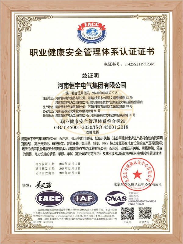
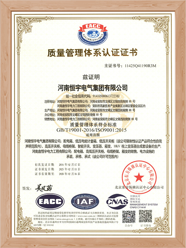
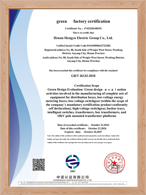
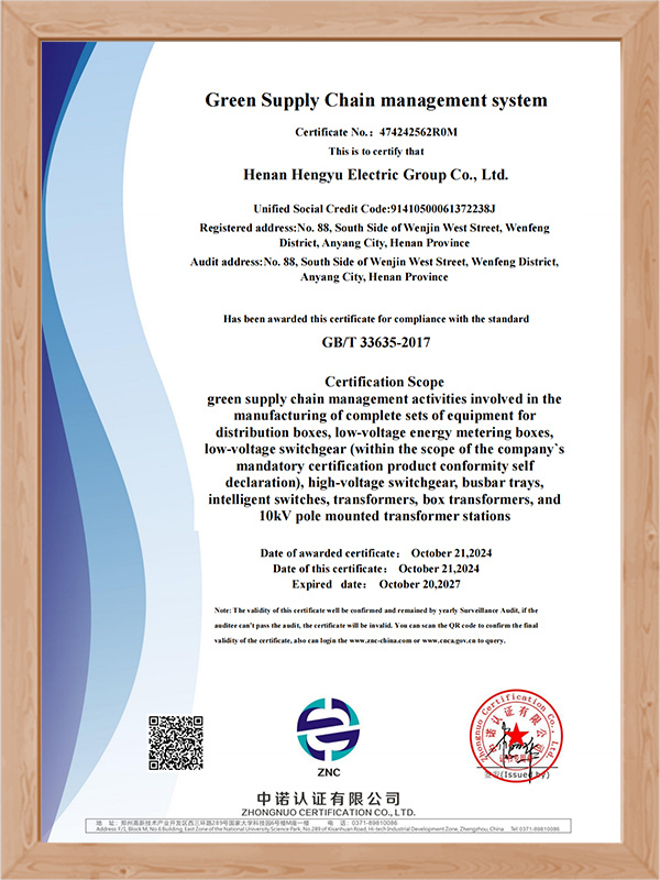
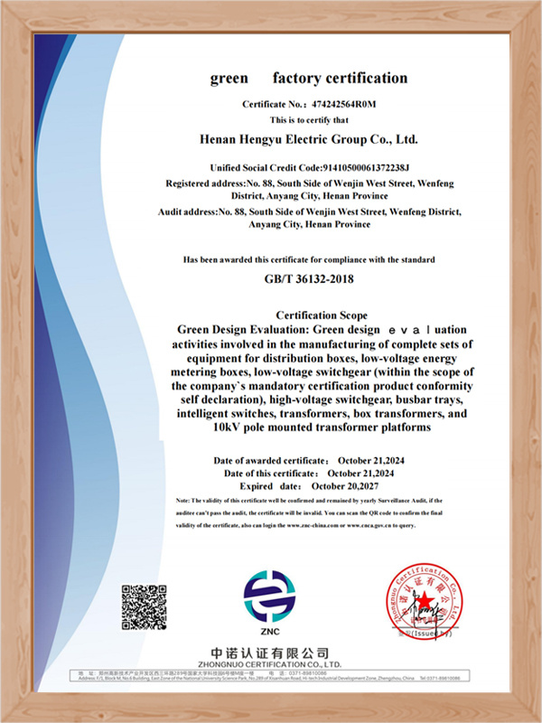
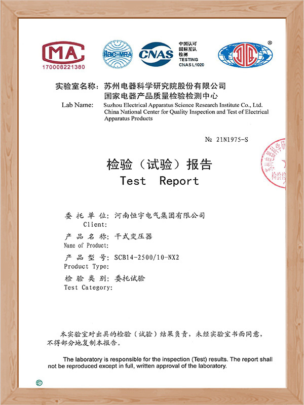
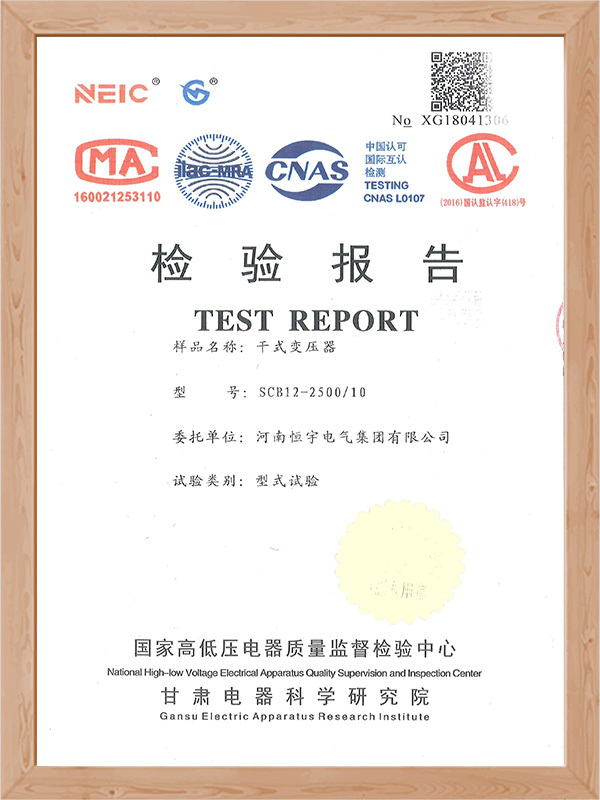
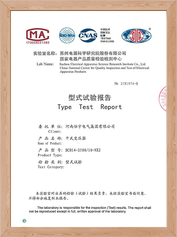
Product Certificate


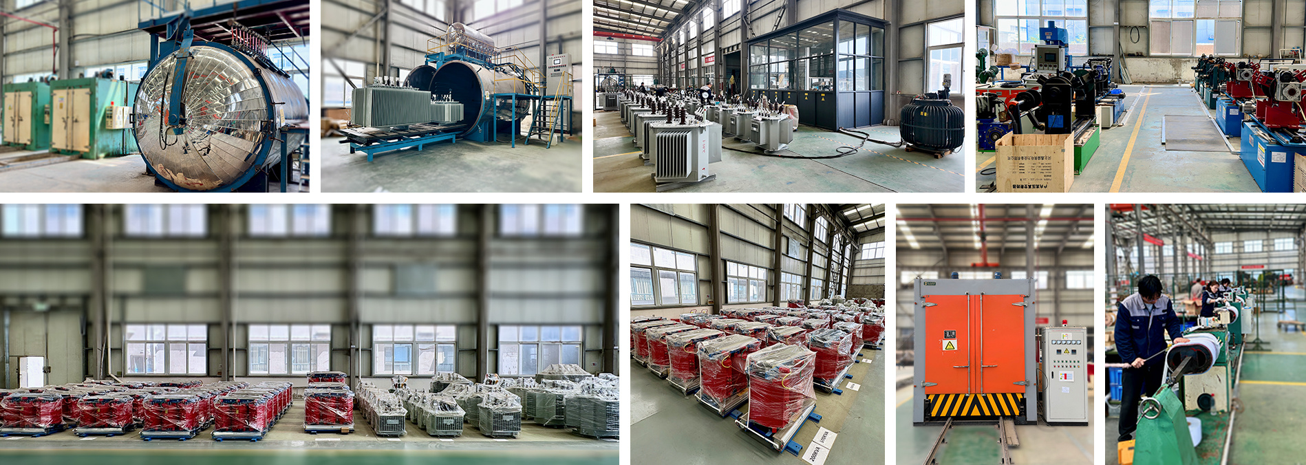
Transformer Workshop
An epoxy resin casting dry-type transformer is a remarkable electrical device with several notable features.

1. Construction and Insulation
It is constructed with epoxy resin casting technology. The epoxy resin serves as an excellent insulator. This not only provides high - voltage insulation but also protects the internal components from environmental factors such as moisture and dust. It helps to ensure the long - term stability and reliability of the transformer.
2. Compact and Space - saving
Compared to some traditional transformers, this dry - type transformer has a relatively compact structure. It can be easily installed in various places, especially in areas where space is limited, such as in modern buildings or industrial plants where every inch of space matters.
3. Safety
The use of epoxy resin makes it a safer option. In case of any internal faults, there is a lower risk of fire or explosion compared to oil - filled transformers. This is crucial for applications in places with high safety requirements, like hospitals, shopping malls, and data centers.
4. Energy Efficiency
These transformers are designed to be energy - efficient. They can help reduce energy losses during the transformation process, which not only saves costs for users but also contributes to environmental protection.
5. Noise Reduction
They are often engineered to produce less noise during operation. This is beneficial for installations in quiet environments, such as residential areas or office buildings, where excessive noise can be a nuisance.
In conclusion, the epoxy resin casting dry-type transformer is an ideal choice for a wide range of applications due to its insulation, compactness, safety, energy - efficiency, and noise - reduction features.
A dry-type transformer is an electrical power distribution device that uses air instead of insulating oil for cooling and insulation. It is designed to provide safe, reliable, and environmentally friendly operation in residential, commercial, and industrial applications. Because it contains no oil, the risk of fire and environmental contamination is significantly reduced, making it suitable for indoor installations such as buildings, hospitals, data centers, and shopping malls. Dry-type transformers feature low maintenance requirements, stable performance, and good thermal resistance. They also offer high mechanical strength, excellent insulation properties, and quiet operation, ensuring efficient and dependable power distribution in modern electrical systems.
6kV, 10kV, SC(B)10 dry-type transformer | ||||||||
model number | Linkage group labeling | Voltage combination (kV) | No-load current (%) | No-load loss(W) | Load loss at different insulation heat resistance levels(W) | Short circuit impedance (%) | ||
B (100°C) | F (120°C) | H (145°C) | ||||||
SC10-30 | Yyn0 | 6~11±2×2.5% | 2.1 | 190 | 670 | 710 | 760 | 4.0 |
SC10-50 | 2.1 | 270 | 940 | 1000 | 1070 | 4.0 | ||
SC10-80 | 1.6 | 370 | 1290 | 1380 | 1480 | 4.0 | ||
SC10-100 | 1.6 | 400 | 1480 | 1570 | 1690 | 4.0 | ||
SC10-125 | 1.5 | 470 | 1740 | 1850 | 1980 | 4.0 | ||
SC10-160 | 1.5 | 540 | 2000 | 2130 | 2280 | 4.0 | ||
SC10-200 | 1.3 | 620 | 2370 | 2530 | 2710 | 4.0 | ||
SC10-250 | 1.3 | 720 | 2590 | 2760 | 2960 | 4.0 | ||
SC10-315 | 1.1 | 880 | 3270 | 3470 | 3730 | 4.0 | ||
SC(B)10-400 | 1.1 | 980 | 3750 | 3990 | 4280 | 4.0 | ||
SC(B)10-500 | 1.1 | 1160 | 4590 | 4880 | 5230 | 4.0 | ||
SC(B)10-630 | 0.9 | 1340 | 5530 | 5880 | 6290 | 4.0 | ||
SC(B)10-630 | 0.9 | 1300 | 5610 | 5960 | 6400 | 6.0 | ||
SC(B)10-800 | 0.9 | 1520 | 6550 | 6960 | 7460 | 6.0 | ||
SC(B)10-1000 | 0.9 | 1770 | 7650 | 8130 | 8760 | 6.0 | ||
SC(B)10-1250 | 0.9 | 2090 | 9100 | 9690 | 10370 | 6.0 | ||
SC(B)10-1600 | 0.9 | 2450 | 11050 | 11730 | 12580 | 6.0 | ||
SC(B)10-2000 | 0.9 | 3050 | 13600 | 14450 | 15560 | 6.0 | ||
SC(B)10-2500 | 0.7 | 3600 | 16150 | 17170 | 18450 | 6.0 | ||
SCB10-1600 | 0.9 | 2450 | 12280 | 12960 | 13900 | 8.0 | ||
SCB10-2000 | 0.7 | 3050 | 15020 | 15960 | 17110 | 8.0 | ||
SCB10-2500 | 0.7 | 3600 | 17760 | 18890 | 20290 | 8.0 | ||
| Note: The above data is only for reference when designing and selecting, and the final data is subject to the real thing. | ||||||||
| 6kV, 10kV, SC(B)11 dry-type transformer | ||||||||
model number | Linkage group labeling | Voltage combination (kV) | No-load current (%) | No-load loss(W) | Load loss at different insulation heat resistance levels (W) | Short circuit impedance (%) | ||
B (100°C) | F (120°C) | H (145°C) | ||||||
SC11-30 | Yyn0 | 6~11±2×2.5% | 1.9 | 170 | 670 | 710 | 760 | 4.0 |
SC11-50 | 1.9 | 240 | 940 | 1000 | 1070 | 4.0 | ||
SC11-80 | 1.5 | 330 | 1290 | 1380 | 1480 | 4.0 | ||
SC11-100 | 1.5 | 360 | 1480 | 1570 | 1690 | 4.0 | ||
SC11-125 | 1.3 | 420 | 1740 | 1850 | 1980 | 4.0 | ||
SC11-160 | 1.3 | 480 | 2000 | 2130 | 2280 | 4.0 | ||
SC11-200 | 1.1 | 550 | 2370 | 2530 | 2710 | 4.0 | ||
SC11-250 | 1.1 | 640 | 2590 | 2760 | 2960 | 4.0 | ||
SC11-315 | 1.0 | 790 | 3270 | 3470 | 3730 | 4.0 | ||
SC(B)11-400 | 1.0 | 880 | 3750 | 3990 | 4280 | 4.0 | ||
SC(B)11-500 | 0.9 | 1040 | 4590 | 4880 | 5230 | 4.0 | ||
SC(B)11-630 | 0.9 | 1200 | 5530 | 5880 | 6290 | 4.0 | ||
SC(B)11-630 | 0.9 | 1170 | 5610 | 5960 | 6400 | 6.0 | ||
SC(B)11-800 | 0.8 | 1360 | 6550 | 6960 | 7460 | 6.0 | ||
SC(B)11-1000 | 0.8 | 1590 | 7650 | 8130 | 8760 | 6.0 | ||
SC(B)11-1250 | 0.8 | 1880 | 9100 | 9690 | 10370 | 6.0 | ||
SC(B)11-1600 | 0.7 | 2200 | 11050 | 11730 | 12580 | 6.0 | ||
SC(B)11-2000 | 0.6 | 2740 | 13600 | 14450 | 15560 | 6.0 | ||
SC(B)11-2500 | 0.6 | 3240 | 16150 | 17170 | 18450 | 6.0 | ||
SCB11-1600 | 0.7 | 2200 | 12280 | 12960 | 13900 | 8.0 | ||
SCB11-2000 | 0.6 | 2740 | 15020 | 15960 | 17110 | 8.0 | ||
SCB11-2500 | 0.6 | 3240 | 17760 | 18890 | 20290 | 8.0 | ||
| Note: The above data is only for reference when designing and selecting, and the final data is subject to the real thing. | ||||||||
| 6kV, 10kV, SC(B)12 dry-type transformer | ||||||||
model number | Linkage group labeling | Voltage combination (kV) | No-load current (%) | No-load loss(W) | Load loss at different insulation heat resistance levels(W) | Short circuit impedance (%) | ||
B (100°C) | F (120°C) | H (145°C) | ||||||
SC12-30 | Yyn0 | 6~11±2×2.5% | 2.4 | 150 | 670 | 710 | 760 | 4.0 |
SC12-50 | 2.4 | 215 | 940 | 1000 | 1070 | 4.0 | ||
SC12-80 | 1.8 | 295 | 1290 | 1380 | 1480 | 4.0 | ||
SC12-100 | 1.8 | 320 | 1480 | 1570 | 1690 | 4.0 | ||
SC12-125 | 1.6 | 375 | 1740 | 1850 | 1980 | 4.0 | ||
SC12-160 | 1.6 | 430 | 2000 | 2130 | 2280 | 4.0 | ||
SC12-200 | 1.4 | 495 | 2370 | 2530 | 2710 | 4.0 | ||
SC12-250 | 1.4 | 575 | 2590 | 2760 | 2960 | 4.0 | ||
SC12-315 | 1.2 | 705 | 3270 | 3470 | 3730 | 4.0 | ||
SC(B)12-400 | 1.2 | 785 | 3750 | 3990 | 4280 | 4.0 | ||
SC(B)12-500 | 1.0 | 930 | 4590 | 4880 | 5230 | 4.0 | ||
SC(B)12-630 | 1.0 | 1070 | 5530 | 5880 | 6290 | 4.0 | ||
SC(B)12-630 | 1.0 | 1040 | 5610 | 5960 | 6400 | 6.0 | ||
SC(B)12-800 | 1.0 | 1215 | 6550 | 6960 | 7460 | 6.0 | ||
SC(B)12-1000 | 1.0 | 1415 | 7650 | 8130 | 8760 | 6.0 | ||
SC(B)12-1250 | 1.0 | 1670 | 9100 | 9690 | 10370 | 6.0 | ||
SC(B)12-1600 | 1.0 | 1960 | 11050 | 11730 | 12580 | 6.0 | ||
SC(B)12-2000 | 0.8 | 2440 | 13600 | 14450 | 15560 | 6.0 | ||
SC(B)12-2500 | 0.8 | 2880 | 16150 | 17170 | 18450 | 6.0 | ||
SCB12-1600 | 1.0 | 1960 | 12280 | 12960 | 13900 | 8.0 | ||
SCB12-2000 | 0.8 | 2440 | 15020 | 15960 | 17110 | 8.0 | ||
SCB12-2500 | 0.8 | 2880 | 17760 | 18890 | 20290 | 8.0 | ||
| Note: The above data is only for reference when designing and selecting, and the final data is subject to the real thing. | ||||||||
| 6kV, 10kV, SC(B)13 dry-type transformer | |||||||||
model number | Rated Capacity | Voltage combinations and tap ranges | Linkage group labeling | No-load loss | Load Loss | No-load current (%) | Short circuit impedance (%) | ||
High voltage | High-voltage tap range (%) | Low voltage (kV) | |||||||
SC(B) 13-30 | 30 | 10 | ±5 | 0.4 | Yyn0 | 135 | 640 | 2.0 | 4.0 |
SC(B)13-50 | 50 | 195 | 900 | 2.0 | |||||
SC(B)13-80 | 80 | 265 | 1240 | 1.5 | |||||
SC(B)13-100 | 100 | 290 | 1410 | 1.5 | |||||
SC(B)13-125 | 125 | 340 | 1660 | 1.3 | |||||
SC(B)13-160 | 160 | 385 | 1910 | 1.3 | |||||
SC(B)13-200 | 200 | 445 | 2270 | 1.1 | |||||
SC(B)13-250 | 250 | 515 | 2480 | 1.1 | |||||
SC(B)13-315 | 315 | 635 | 3120 | 1.0 | |||||
SC(B)13-400 | 400 | 705 | 3590 | 1.0 | |||||
SC(B)13-500 | 500 | 835 | 4390 | 1.0 | |||||
SC(B)13-630 | 630 | 965 | 5290 | 0.85 | |||||
SC(B)13-630 | 630 | 935 | 5360 | 0.85 | 6.0 | ||||
SC(B)13-800 | 800 | 1090 | 6260 | 0.85 | |||||
SC(B)13-1000 | 100 | 1270 | 7310 | 0.85 | |||||
SC(B)13-1250 | 1250 | 1500 | 8720 | 0.85 | |||||
SC(B)13-1600 | 1600 | 1760 | 10500 | 0.85 | |||||
SC(B)13-2000 | 2000 | 2190 | 13,000 | 0.7 | |||||
SC(B)13-2500 | 2500 | 2590 | 15400 | 0.7 | |||||
| Note: The above data is only for reference when designing and selecting, and the final data is subject to the real thing. | |||||||||
| 6kV, 10kV, SC(B)14 dry-type transformer | ||||||||||
Rated capacity (kVA) | High voltage | High voltage tap range | Low voltage | Linkage group labeling | Electrical Steel Strip | No-load current | Short Circuit Impedance | |||
No-load loss | Load Loss | |||||||||
B (100°C) | F (120°C) | H (145°C) | ||||||||
30 | 6 | ±2×2.5 | 0.4 | Dyn11 | 130 | 605 | 640 | 685 | 2.00 | 4.0 |
50 | 185 | 845 | 900 | 965 | 2.00 | |||||
80 | 250 | 1160 | 1240 | 1330 | 1.50 | |||||
100 | 270 | 1330 | 1415 | 1520 | 1.50 | |||||
125 | 320 | 1565 | 1665 | 1780 | 1.30 | |||||
160 | 365 | 1800 | 1915 | 2050 | 1.30 | |||||
200 | 420 | 2135 | 2275 | 2440 | 1.10 | |||||
250 | 490 | 2330 | 2485 | 2665 | 0.90 | |||||
315 | 600 | 2945 | 3125 | 3355 | 0.80 | |||||
400 | 665 | 3375 | 3590 | 3850 | 0.80 | |||||
500 | 790 | 4130 | 4390 | 4705 | 0.70 | |||||
630 | 910 | 4975 | 5290 | 5660 | 0.70 | 6.0 | ||||
630 | 885 | 5050 | 5365 | 5760 | 0.70 | |||||
800 | 1035 | 5895 | 6265 | 6715 | 0.70 | |||||
1000 | 1205 | 6885 | 7315 | 7885 | 0.70 | |||||
1250 | 1420 | 8190 | 8720 | 9335 | 0.70 | |||||
1600 | 1665 | 9945 | 10555 | 11320 | 0.70 | |||||
2000 | 2075 | 12240 | 13005 | 14005 | 0.70 | |||||
2500 | 2450 | 14535 | 15445 | 16605 | 0.70 | |||||
| Note: The above data is only for reference when designing and selecting, and the final data is subject to the real thing. | ||||||||||
| 6kV, 10kV, SC(B)18 dry-type transformer | ||||||||||
Rated Capacity | High voltage | High-voltage tap range | Low Voltage | Linkage group labeling | Electrical Steel Strip | No-load current | Short Circuit Impedance | |||
No-load loss(W) | Load Loss(W) | |||||||||
B (100°C) | F (120°C) | H (145°C) | ||||||||
30 | 6 | ±2×2.5 | 0.4 | Dyn11 | 105 | 605 | 640 | 685 | 2.00 | 4.0 |
50 | 155 | 845 | 900 | 965 | 2.00 | |||||
80 | 210 | 1160 | 1240 | 1330 | 1.50 | |||||
100 | 230 | 1330 | 1415 | 1520 | 1.50 | |||||
125 | 270 | 1565 | 1665 | 1780 | 1.30 | |||||
160 | 310 | 1800 | 1915 | 2050 | 1.30 | |||||
200 | 360 | 2135 | 2275 | 2440 | 1.10 | |||||
250 | 415 | 2330 | 2485 | 2665 | 0.90 | |||||
315 | 510 | 2945 | 3125 | 3355 | 0.80 | |||||
400 | 570 | 3375 | 3590 | 3850 | 0.80 | |||||
500 | 670 | 4130 | 4390 | 4705 | 0.80 | |||||
630 | 775 | 4975 | 5290 | 5660 | 0.70 | |||||
630 | 750 | 5050 | 5365 | 5760 | 0.70 | 6.0 | ||||
800 | 875 | 5895 | 6265 | 6715 | 0.70 | |||||
1000 | 1020 | 6885 | 7315 | 7885 | 0.70 | |||||
1250 | 1205 | 8190 | 8720 | 935 | 0.70 | |||||
1600 | 1415 | 9945 | 10555 | 11320 | 0.70 | |||||
2000 | 1760 | 12240 | 13005 | 14005 | 0.70 | |||||
2500 | 2080 | 14535 | 15445 | 16605 | 0.70 | |||||
| Note: The above data is only for reference when designing and selecting, and the final data is subject to the real thing. | ||||||||||
Recommend Products
Consult
We will offer custom quotes and powerful solutions to meet your needs. Send us your details and we'll get back to you as soon as possible.

Contact Us
Amy : +86 152 2613 0307
No.88 Wenjin West Street, WenfengDistrict, Anyang City, Henan Province, China 455099


Request Quote
Simply tell us what you need — our team will get back to you with a personalized quotation and technical support.